
Reverse Engineering an RX-7 Indicator Stalk
Welcome to the NOVL blog!
I am super excited to finally launch the NOVL blog where I’ll be showcasing innovative projects, talking about trends in digital manufacturing, and sharing some of my passion for digital design and make.
For this post, I’ll show you an example of where I used photogrammetry combined with some manual measurements to remanufacture the indicator stalk for my 1990 Mazda RX-7 (her name is Hannah [Savana] for those rotary fans).

What is Reverse Engineering?
Reverse engineering with 3D scanning is comparable to recreating a part without having the original blueprint. Imagine you have a gear or component from a device, and you want to understand its details for improvement or replacement. While you can dismantle it and take manual measurements, chances are that the geometry is too complex for these measurements to adequately capture the original geometry. This is where you need a means of 3D scanning the component - it's like using a digital scanner that captures every curve, contour, and dimension of the part. Depending on the method of scanning (e.g., photogrammetry, structured light, laser), the dimensions can be taken from the digital model with a high level of accuracy eliminating the need to take any manual measurements. From here, you can use specialised software tools that will assist in ‘redrawing’ the CAD geometry, and go even further to modify or improve the part. It's a bit like creating a digital clone, helping to comprehend the precise design and functionality of a part, whether it's for enhancing performance, ensuring compatibility, or solving engineering challenges.
3D Scanning the Original Part
Now, since the original indicator stalk was broken, I needed to scan a few broken pieces to build the whole model. For this project I used the Phomo platform together with a combination of tools from Autodesk including Meshmixer, Fusion 360, and Recap Photo. The first step was to obtain a suitably accurate 3D mesh of the broken pieces. What is suitably accurate? In the case of this component, the main objective was aesthetic - does it look like the OEM part? The interfaces are important too, however being a plastic injection moulded part, we have a bit of flexibility, especially since it’s a one-off rebuild which can be adjusted.
Introducing Phomo!
I’d like to take this opportunity to introduce you to Phomo, our new platform, which makes professional reality capture and 3D scanning more accessible than ever before! Phomo is essentially an all-in-one hardware and software platform designed to fully automate the photogrammetry pipeline. We’ve just launched a new website and are signing on users for early access. Check it out for more examples of models generated using Phomo.

Original (broken) OEM indicator stalk, held together with Blu-Tak and sprayed with 3D scanning antireflective spray.
To obtain the model I used Phomo to take over 100 photos of each broken piece and these became inputs to Recap Photo. A couple of details here; firstly I sprayed the parts with antireflective spray for scanning. This effectively reduces any specular highlights in the photos, thus helping the photogrammetry algorithm produce a good result. Second, thanks to Phomo, I had a means of automating the photo acquisition which took less than 10 minutes (anything to avoid walking around an object taking hundreds of photos).
The resulting model is shown below (click play to interact with the 3D model). I was impressed with the quality of the mesh that photogrammetry could output and the details of the textures even show my fingerprints all over it!

Scanned mesh of original (using photogrammetry method).
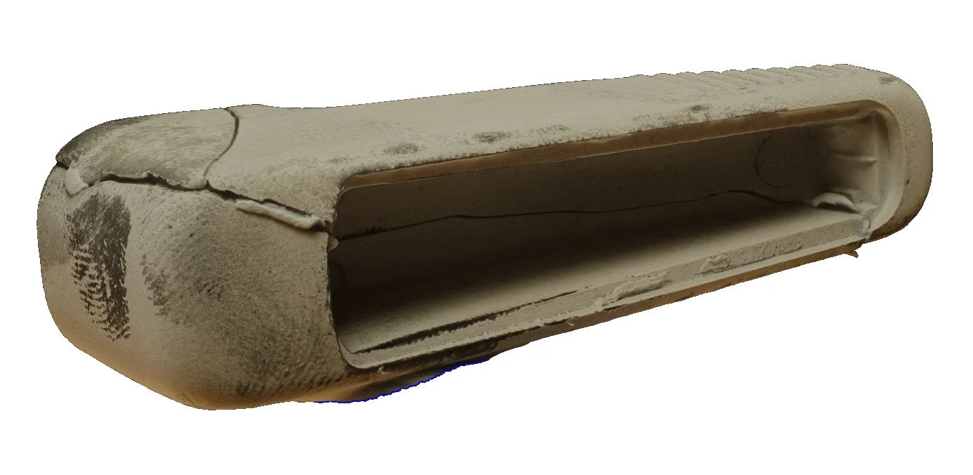
Interactive 3D model of scanned original.
Remodelling the CAD Geometry
This was the time consuming activity. To remodel this component, I used Autodesk Fusion 360 which now has a powerful mesh workspace allowing users to overlay mesh and CAD models. I acknowledge that while Fusion 360 was effective in this project, more complicated or precise reverse engineering projects would need more specialist tools like Oqton’s Geomagic Design X.
The general approach using Fusion 360 was to pick a well-defined plane on the scan mesh as a starting datum. In this case, I used the top surface of the indicator. I created a plane using the mesh points and continued to do the same for the face and the bottom surface. In a very iterative process, I began to draw surface geometry to match the intersecting mesh. For example the face has a cutout which can be effectively ‘traced’ using sketches.
Slowly but surely, I worked through the various bits of geometry paying special attention to the interfaces. In a few instances, I used my calipers to verify individual dimensions.

Scan mesh and remodelled CAD

Remodelled CAD showing interfaces

After modelling the main body of the stalk, I re-drew the markings on the stalk as a vector graphic using Inkscape. This wasn’t completely necessary for this project as only the main body was broken. It also made the 3D models and renders look especially nice! Click the play button below to interact with the reproduced CAD.


Remaking the Part
While the CAD models for this part could be manufactured at scale with the right materials and (some pretty complex) injection mould tooling, I decided to give it a shot using my trusty CR10S-Pro FDM 3D printer with eSun PLA+ filament. For structural integrity, I printed the main body as solid (100% infill) and used an epoxy coating to achieve the smooth surface. I checked how well the stalk connected to the indicator module and was delighted to have the interfaces fit perfectly. Lastly, after a lot of sanding, an undercoat, more sanding, and then a black top coat, I ended up with a result that I’d be happy to see on the car!


Summing up…
This was a great project to test the efficacy of photogrammetry applied to reverse engineering projects where tolerances are quite flexible. The photogrammetry method gave an excellent mesh from which the CAD model was regenerated. It captured all interfaces and curvature to ultimately recreate a model that was indistinguishable from the OEM part.
Do you have a reverse engineering challenge that needs a NOVL solution? Get in touch!